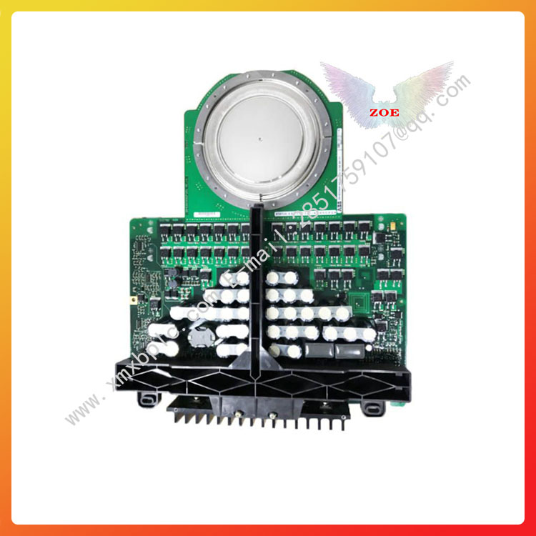
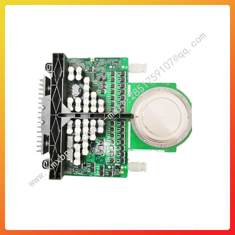
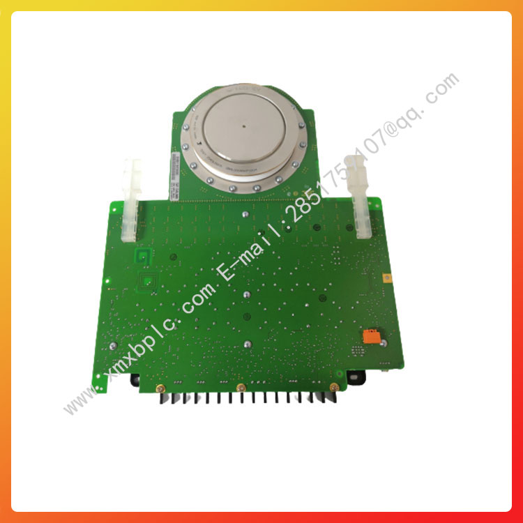
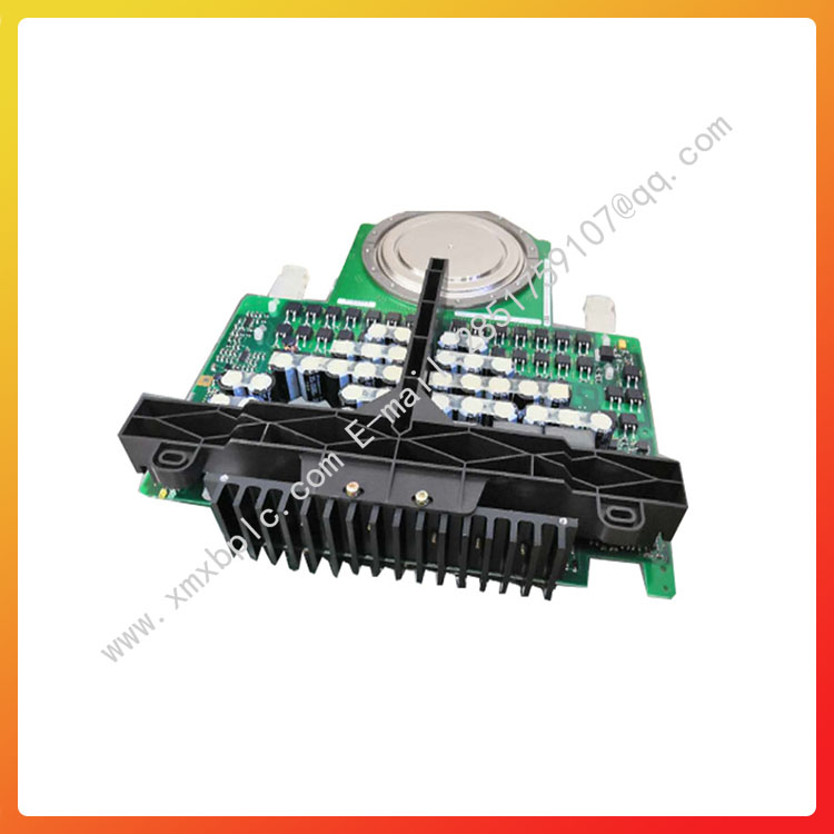
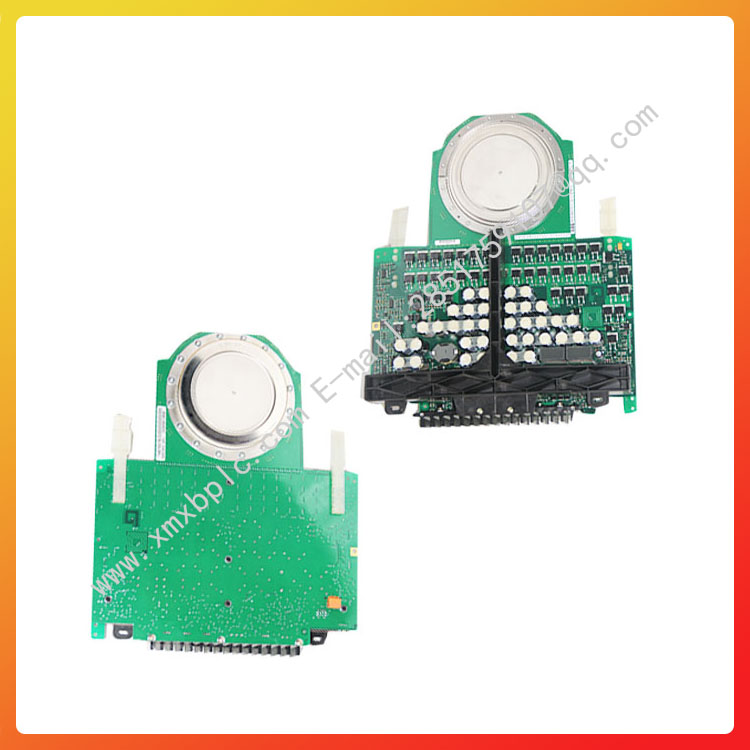
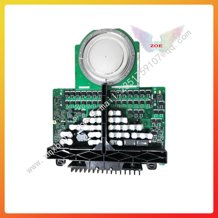
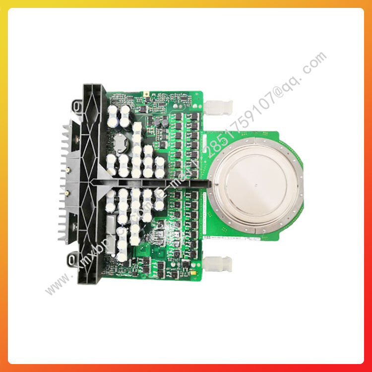
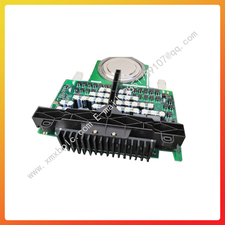
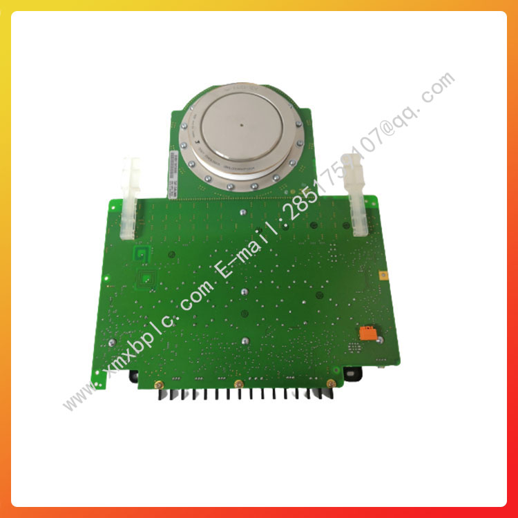
3BHB005243R0105 ABB IGCT可控硅 SattControl系统模块的相关参数
3BHB013085R0001 型号
一般信息
产品编号:3BHB013085R0001
ABB型号:5HY3545L0009
目录描述:5HY3545L0009;IGCT模块
详细描述:5HY3545L0009
类别
零件与服务»驱动器»服务»备件和耗材»零件
3BHB013085R0001-图像0
使用位置(作为套件的一部分)
订购
核心信用:0.00
原产国:瑞士(CH)
海关税则编号:85413000
发票描述:IGCT模块
定制:否
小订单数量:1件
订单数量:1件
仅报价:否
销售计量单位:件
容器信息
总容积:0 m³
尺寸
产品净重:3.4千克
包装级别1单元:1个
技术的
框架尺寸:Spare_Parts
其他信息
产品名称:IGCT模块
分类
联合国秘书长:32111700
可控硅的主要参数:
1,额定通态电流(IT)即大稳定工作电流,俗称电流。常用可控硅的IT一般为一安到几十安。
2,反向重复峰值电压(VRRM)或断态重复峰值电压(VDRM),俗称耐压。常用可控硅的VRRM/VDRM一般为几百伏到一千伏。
3,控制极触发电流(IGT),俗称触发电流。常用可控硅的IGT一般为几微安到几十毫安。
作用盘点:
1.普通晶闸管基本的用途就是可控整流。
大家熟悉的二极管整流电路属于不可控整流电路。如果把二极管换成晶闸管,就可以构成可控整流电路。以简单的单相半波可控整流电路为例,在正弦交流电压U2的正半周期间,如果VS的控制极没有输入触发脉冲Ug,VS仍然不能导通,只有在U2处于正半周,在控制极外加触发脉冲Ug时,晶闸管被触发导通。
2.可控硅主要的作用之一就是稳压稳流。
可控硅在自动控制控制,机电领域,工业电气及家电等方面都有广泛的应用。可控硅是一种有源开关元件,平时它保持在非道通状态,直到由一个较少的控制信号对其触发或称“点火”使其道通,一旦被点火就算撤离触发信号它也保持道通状态,要使其截止可在其阳极与阴极间加上反向电压或将流过可控硅二极管的电流减少到某一个值以下。
3.可控硅是一种可控的大功率半导体器件。主要用于可控整流、变频、交流调压、逆变和无触头开关。
如ABB 5SHX1960L0004系列型号,用于可控硅和压缩机
工作原理
结构原件
可控硅是P1N1P2N2四层三端结构元件,共有三个PN结,分析原理时,可以把它看作由一个PNP管和一个NPN管所组成,其等效图解如右图所示。双向可控硅:双向可控硅是一种硅可控整流器件,也称作双向晶闸管。这种器件在电路中能够实现交流电的无触点控制,以小电流控制大电流,具有无火花、动作快、寿命长、可靠性高以及简化电路结构等优点。从外表上看,双向可控硅和普通可控硅很相似,也有三个电极。但是,它除了其中一个电极G仍叫做控制极外,另外两个电极通常却不再叫做阳极和阴极,而统称为主电极Tl和T2。它的符号也和普通可控硅不同,是把两个可控硅反接在一起画成的,如图2所示。它的型号,在我国一般用“3CTS”或“KS”表示;国外的资料也有用“TRIAC”来表示的。双向可控硅的规格、型号、外形以及电极引脚排列依生产厂家不同而有所不同,但其电极引脚多数是按T1、T2、G的顾序从左至右排列(观察时,电极引脚向下,面对标有字符的一面)。市场上常见的几种塑封外形结构双向可控硅的外形及电极引脚排列如下图1所示。
晶闸管特性
为了能够直观地认识晶闸管的工作特性,大家先看这块示教板(图3)。晶闸管VS与小灯泡EL串联起来,通过开关S接在直流电源上。注意阳极A是接电源的正极,阴极K接电源的负极,控制极G通过按钮开关SB接在1.5V直流电源的正极(这里使用的是KP1型晶闸管,若采用KP5型,应接在3V直流电源的正极)。晶闸管与电源的这种连接方式叫做正向连接,也就是说,给晶闸管阳极和控制极所加的都是正向电压。合上电源开关S,小灯泡不亮,说明晶闸管没有导通;再按一下按钮开关SB,给控制极输入一个触发电压,小灯泡亮了,说明晶闸管导通了。这个演示实验给了我们什么启发呢?
这个实验告诉我们,要使晶闸管导通,一是在它的阳极A与阴极K之间外加正向电压,二是在它的控制极G与阴极K之间输入一个正向触发电压。晶闸管导通后,松开按钮开关,去掉触发电压,仍然维持导通状态。
晶闸管特点
“一触即发”。但是,如果阳极或控制极外加的是反向电压,晶闸管就不能导通。控制极的作用是通过外加正向触发脉冲使晶闸管导通,却不能使它关断。那么,用什么方法才能使导通的晶闸管关断呢?使导通的晶闸管关断,可以断开阳极电源(图3中的开关S)或使阳极电流小于维持导通的小值(称为维持电流)。如果晶闸管阳极和阴极之间外加的是交流电压或脉动直流电压,那么,在电压过零时,晶闸管会自行关断。
应用类型
图4示出了双向可控硅的特性曲线。
由图可见,双向可控硅的特性曲线是由一、三两个象限内的曲线组合成的。象限的曲线说明当加到主电极上的电压使Tc对T1的极性为正时,我们称为正向电压,并用符号U21表示。当这个电压逐渐增加到等于转折电压UBO时,图3(b)左边的可控硅就触发导通,这时的通态电流为I21,方向是从T2流向Tl。从图中可以看到,触发电流越大,转折电压就越低,这种情形和普通可控硅的触发导通规律是一致的,当加到主电极上的电压使Tl对T2的极性为正时,叫做反向电压,并用符号U12表示。当这个电压达到转折电压值时,图3(b)右边的可控硅便触发导通,这时的电流为I12,其方向是从T1到T2。这时双向可控硅的特性曲线,
由于在双向可控硅的主电极上,无论加以正向电压或是反向电压,也不管触发信号是正向还是反向,它都能被触发导通,因此它有以下四种触发方式:
(1)当主电极T2对Tl所加的电压为正向电压,控制极G对电极Tl所加的也是正向触发信号(图5a)。双向可控硅触发导通后,电流I2l的方向从T2流向T1。由特性曲线可知,这时双向可控硅触发导通规律是按第二象限的特性进行的,又因为触发信号是正向的,所以把这种触发叫做“象限的正向触发”或称为I+触发方式。
(2)如果主电极T2仍加正向电压,而把触发信号改为反向信号(图5b),这时双向可控硅触发导通后,通态电流的方向仍然是从T2到T1。我们把这种触发叫做“象限的负触发”或称为I-触发方式。
(3)两个主电极加上反向电压U12(图5c),输入正向触发信号,双向可控硅导通后,通态电流从T1流向T2。双向可控硅按第三象限特性曲线工作,因此把这种触发叫做Ⅲ+触发方式。
(4)两个主电极仍然加反向电压U12,输入的是反向触发信号(图5d),双向可控硅导通后,通态电流仍从T1流向T2。这种触发就叫做Ⅲ-触发方式。双向可控硅虽然有以上四种触发方式,但由于负信号触发所需要的触发电压和电流都比较小。工作比较可靠,因此在实际使用时,负触发方式应用较多。
The main parameters of thyristor:
1. Rated on state current (IT) refers to the maximum stable operating current, commonly known as current. The IT of commonly used thyristor is generally from one ampere to several tens of amperes.
2. Reverse repetitive peak voltage (VRRM) or off state repetitive peak voltage (VDRM), commonly known as withstand voltage. The VRRM/VDRM of commonly used controllable silicon is generally from several hundred volts to one thousand volts.
3. Control pole trigger current (IGT), commonly known as trigger current. The IGT of commonly used thyristor is generally from a few microamps to tens of milliamps.
Function inventory:
The most basic use of ordinary thyristors is controllable rectification.
The familiar diode rectifier circuit belongs to an uncontrollable rectifier circuit. If the diode is replaced with a thyristor, a controllable rectifier circuit can be formed. Taking the simplest single-phase half wave controllable rectifier circuit as an example, during the positive half cycle of the sinusoidal AC voltage U2, if the control pole of VS does not input the trigger pulse Ug, VS still cannot conduct. Only when U2 is in the positive half cycle and the trigger pulse Ug is applied to the control pole, the thyristor is triggered to conduct.
One of the main functions of thyristor is to stabilize voltage and current.
Thyristors are widely used in automatic control, electromechanical fields, industrial electrical, and home appliances. Thyristor is an active switching element that remains in a non channel state until triggered or "ignited" by a relatively small control signal. Once ignited, even if the trigger signal is withdrawn, it remains in a channel state. To cut it off, a reverse voltage can be applied between its anode and cathode or the current flowing through the thyristor diode can be reduced to a certain value below.
3. Thyristor is a controllable high-power semiconductor device. Mainly used for controllable rectification, frequency conversion, AC voltage regulation, inverter, and contactless switches.
ABB 5SHX1960L0004 series models, used for thyristor and compressors
working principle
Structural elements
Thyristor is a P1N1P2N2 four layer three terminal structural element with three PN junctions. When analyzing the principle, it can be regarded as composed of a PNP transistor and an NPN transistor, and its equivalent diagram is shown in the right figure. Bidirectional thyristor: Bidirectional thyristor is a silicon controlled rectifier device, also known as a bidirectional thyristor. This device can achieve contactless control of AC power in circuits, controlling large currents with small currents. It has the advantages of no sparks, fast action, long service life, high reliability, and simplified circuit structure. From the appearance, bidirectional thyristor is very similar to ordinary thyristor, with three electrodes. However, except for one electrode G, which is still called the control electrode, the other two electrodes are usually no longer called the anode and cathode, but collectively referred to as the main electrodes Tl and T2. Its symbol is also different from that of ordinary thyristors, which is drawn by reversing the connection of two thyristors together, as shown in Figure 2. Its model is generally represented by "3CTS" or "KS" in China; Foreign data can also be represented by 'TRIAC'. The specifications, models, appearance, and electrode pin arrangement of bidirectional thyristor vary depending on the manufacturer, but most of its electrode pins are arranged from left to right in the order of T1, T2, and G (when observed, the electrode pins are facing downwards and facing the side marked with characters). The appearance and electrode pin arrangement of the most common plastic encapsulated structure bidirectional thyristor in the market are shown in Figure 1.
Thyristor characteristics
In order to intuitively understand the working characteristics of thyristors, let's take a look at this teaching board (Figure 3). The thyristor VS is connected in series with the small light bulb EL and connected to the DC power supply through switch S. Note that anode A is connected to the positive pole of the power supply, cathode K is connected to the negative pole of the power supply, and control electrode G is connected to the positive pole of the 1.5V DC power supply through button switch SB (here, KP1 type thyristors are used, and if KP5 type thyristors are used, they should be connected to the positive pole of the 3V DC power supply). The connection method between the thyristor and the power supply is called forward connection, which means that the positive voltage is applied to both the anode and control poles of the thyristor. Turn on the power switch S, but the small light bulb does not light up, indicating that the thyristor is not conducting; Press the button switch SB again to input a triggering voltage to the control pole. The small light bulb lights up, indicating that the thyristor is conducting. What inspiration did this demonstration experiment give us?
This experiment tells us that to make the thyristor conductive, one is to apply a forward voltage between its anode A and cathode K, and the other is to input a forward trigger voltage between its control electrode G and cathode K. After the thyristor is turned on, release the button switch, remove the triggering voltage, and still maintain the conduction state.
Characteristics of thyristors
At a touch. However, if a reverse voltage is applied to the anode or control electrode, the thyristor cannot conduct. The function of the control pole is to turn on the thyristor by applying a forward trigger pulse, but it cannot be turned off. So, what method can be used to turn off the conducting thyristor? By turning off the conducting thyristor, the anode power supply (switch S in Figure 3) can be disconnected or the anode current can be reduced to the minimum value required to maintain continuity (referred to as the maintenance current). If there is an AC voltage or pulsating DC voltage applied between the anode and cathode of the thyristor, the thyristor will automatically turn off when the voltage crosses zero.
Application Type
Figure 4 shows the characteristic curve of bidirectional thyristor.
As shown in the figure, the characteristic curve of bidirectional thyristor is composed of curves within the first and third quadrants. The curve in the first quadrant indicates that when the voltage applied to the main electrode causes Tc to have a positive polarity towards T1, it is called the forward voltage and represented by the symbol U21. When this voltage gradually increases to the turning point voltage UBO, the thyristor on the left side of Figure 3 (b) triggers conduction, and the on state current at this time is I21, flowing from T2 to Tl. From the figure, it can be seen that the larger the triggering current, the lower the turning voltage. This situation is consistent with the triggering conduction law of ordinary thyristor. When the voltage applied to the main electrode causes Tl to have a positive polarity towards T2, it is called a reverse voltage and is represented by the symbol U12. When this voltage reaches the turning point voltage value, the thyristor on the right side of Figure 3 (b) triggers conduction, and the current at this time is I12, with a direction from T1 to T2. At this point, the characteristic curve of the bidirectional thyristor,
Due to the fact that on the main electrode of the bidirectional thyristor, it can be triggered to conduct regardless of whether the forward or reverse voltage is applied, and whether the trigger signal is forward or reverse, it has the following four triggering methods:
(1) When the voltage applied by the main electrode T2 to Tl is a forward voltage, the voltage applied by the control electrode G to the first electrode Tl is also a forward trigger signal (Figure 5a). After the bidirectional thyristor triggers conduction, the direction of current I2l flows from T2 to T1. From the characteristic curve, it can be seen that the conduction law of the bidirectional thyristor trigger is carried out according to the characteristics of the second quadrant, and because the trigger signal is in the forward direction, this trigger is called the "first quadrant forward trigger" or the I+trigger method.
(2) If the forward voltage is still applied to the main electrode T2 and the trigger signal is changed to a reverse signal (Figure 5b), then after the bidirectional thyristor triggers conduction, the direction of the on state current is still from T2 to T1. We call this trigger the "first quadrant negative trigger" or the I-trigger method.
(3) Two main electrodes are applied with a reverse voltage U12 (Figure 5c), and a forward trigger signal is input. After the bidirectional thyristor is turned on, the on state current flows from T1 to T2. The bidirectional thyristor operates according to the third quadrant characteristic curve, so this trigger is called the III+trigger method.
(4) The two main electrodes still apply reverse voltage U12, and the input is a reverse trigger signal (Figure 5d). After the bidirectional thyristor is turned on, the on state current still flows from T1 to T2. This trigger is called the III trigger method. Although bidirectional thyristor has the above four triggering methods, the triggering voltage and current required for negative signal triggering are relatively small. The work is relatively reliable, so negative triggering methods are widely used in practical use.


基他相关型号:
| ABB | PPD11 | ICS TRIPLEX | T9481 | |
| ABB | PPD113 B01-10-150000 | ICS TRIPLEX | T9451 | |
| ABB | PPD113 B03-26-100110 | ICS TRIPLEX | T9432 | |
| ABB | PPD115A102 | ICS TRIPLEX | T9402 | |
| ABB | LDGRB-01 | ICS TRIPLEX | T9310-02 PN-175486 | |
| ABB | XVC517AE02 | ICS TRIPLEX | T9310-02 | |
| ABB | ICS TRIPLEX | T9110 | ||
| ABB | UNITROL5000 | ICS TRIPLEX | T8480C | |
| ABB | UNITROL1010 | ICS TRIPLEX | T8461 | |
| ABB | UNS0121A-2 | ICS TRIPLEX | T8451 | |
| ABB | PP886 | ICS TRIPLEX | T8431C | |
| ABB | XVC517AE02 | ICS TRIPLEX | T8431 | |
| ABB | PPD512 A10-454000 | ICS TRIPLEX | T8403C | |
| ABB | 5SHX2645L0002 | ICS TRIPLEX | T8403 | |
| ABB | KUC755AE105 | ICS TRIPLEX | T8314 | |
| ABB | PM510V16 3BSE008358R1 | ICS TRIPLEX | T8312-4 | |
| ABB | PM866AK01 | ICS TRIPLEX | T8311 | |
| ABB | PPD115A102 | ICS TRIPLEX | T9100 | |
| ABB | PFSK151 | ICS TRIPLEX | 5SHY3545L0009 3BHB005243R0105 | |
| A-B | 1753-L32BBBM-8A | TRICONEX | 3721 | |
| A-B | 1407-CGCM | A-B | 1394C-SJT22-A | |
| Emerson | EPSCPE100 | A-B | 1753-L32BBBM-8A | |
| FOXBORO | FBM233 P0926GX | A-B | 1753-L32BBBM-8A | |
| A-B | 80026-044-06 | A-B | 1407-CGCM |


 客服1
客服1