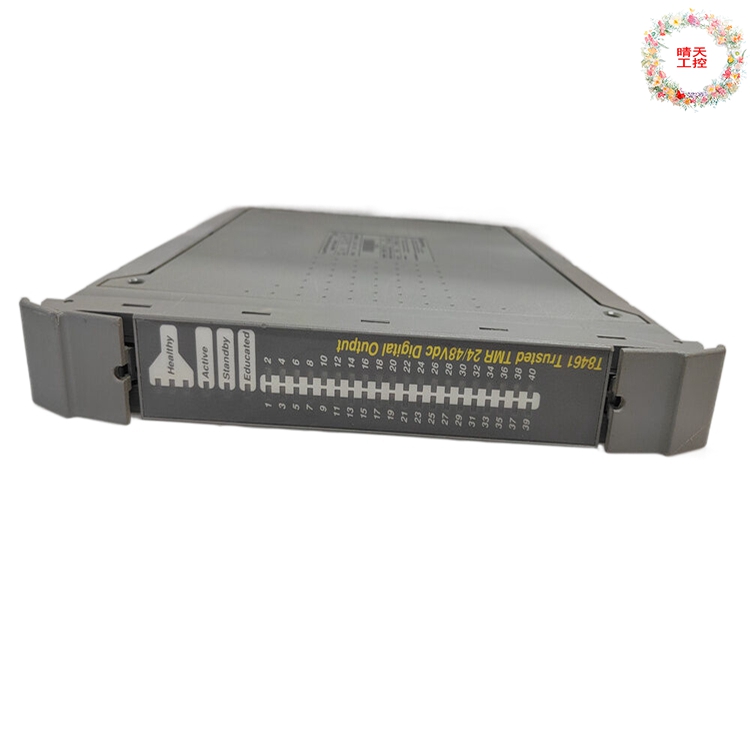

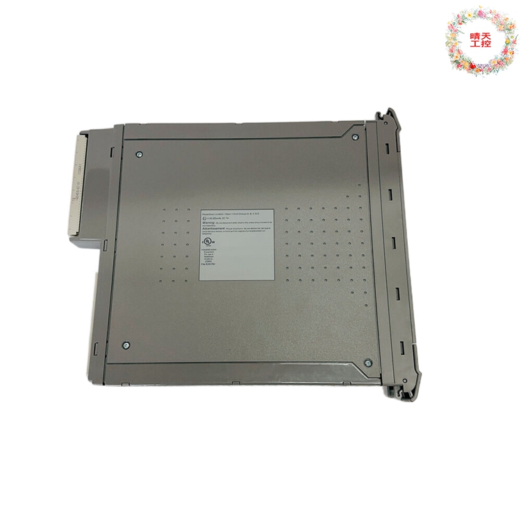

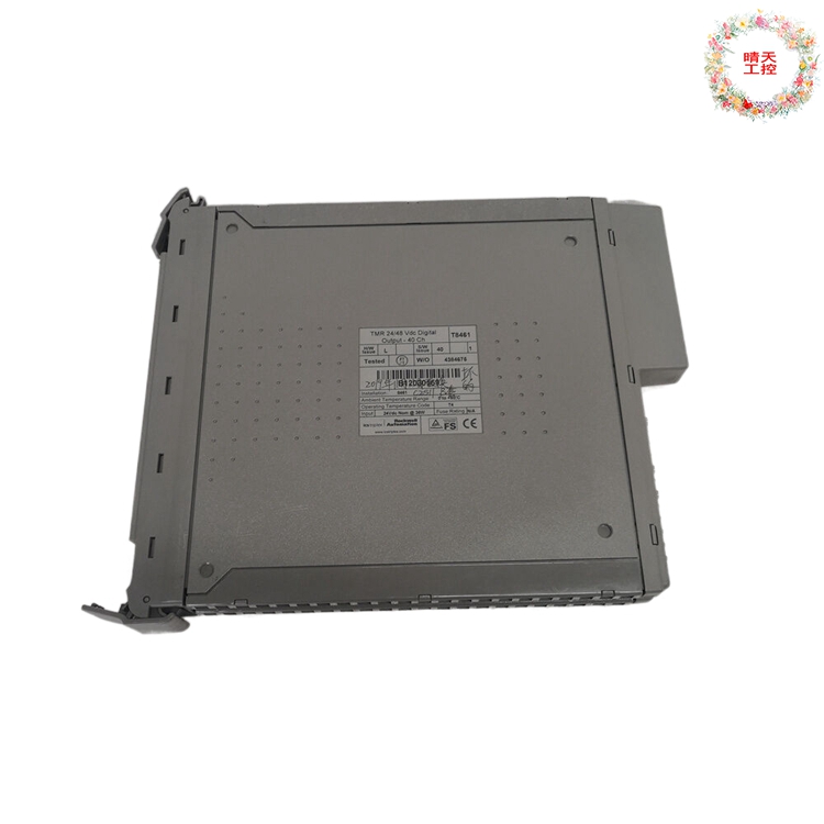
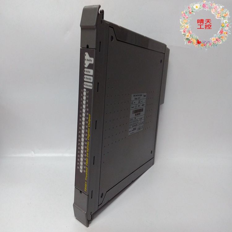
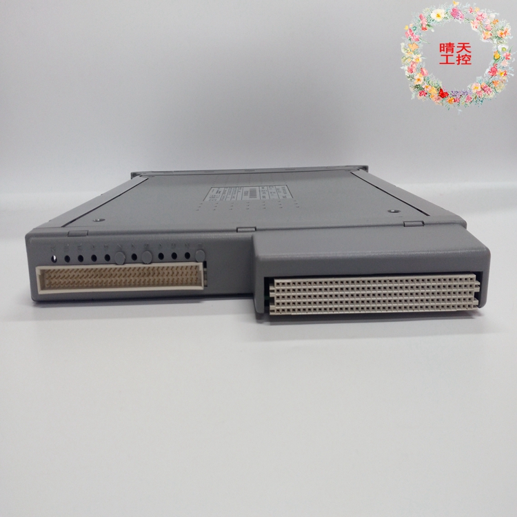
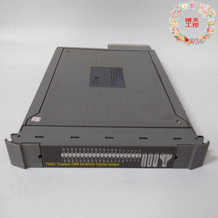
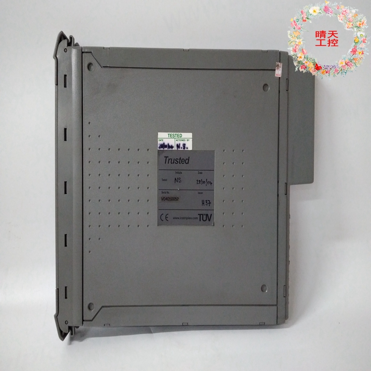
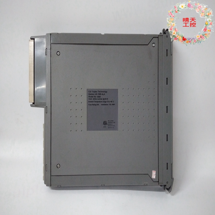
T8461 ICS TRIPLEX T8451 输入/输出信号处理
产品信息
制造商: ICS TRIPLEX
原产地:美国
型号: T8461
基本信息:输入输出模块
付款条件:电汇
服务: 一年保修
标准交货时间出厂:现货
全球运输:联邦快递,顺丰快递,京东快递,德邦快递国内外运输。
可信TMR扩展器处理器
产品概述
Trusted®TMR扩展器处理器模块位于Trusted的处理器插槽中
扩展器机箱,并在扩展器总线和扩展器之间提供“从”接口
机箱背板。扩展器总线允许使用
非屏蔽双绞线(UTP)电缆连接,同时保持容错、高
带宽模块间总线(IMB)功能。
模块为膨胀机总线、模块本身和膨胀机提供故障控制
底盘,确保这些潜在故障的影响是局部的,并确保系统可用性
大化。该模块具有HIFT TMR架构的容错功能。全面的诊断,
监控和测试提供了快速的故障识别。热备用和模块备用
支持配置,允许自动和手动修复策略
特征:
•三模冗余(TMR)、容错(3-2-0)操作。
•硬件实现的容错(HIFT)体系结构。
•专用的硬件和软件测试制度,可提供非常快速的故障识别和
响应时间。
•自动故障处理,无干扰报警。
•热更换。
•显示模块运行状况和状态的前面板指示灯
要安装模块,请执行以下操作:
1.确保电缆总成的位置正确。
2.使用释放键释放模块上的弹出器卡舌。确保推料器
选项卡完全打开。
3.握住弹出器,小心地将模块插入预期插槽。
4.按压模块蒙皮的顶部和底部,将模块完全推入原位。
5.关闭模块弹出器,确保它们卡入锁定位置。
2.2.模块更换
更换模块必须插入空闲的处理器插槽中,确保
模块位置正确,弹出器卡舌关闭(请参阅模块插入和
拆卸)。新安装的模块将执行其通电顺序。
确保新安装的模块上的发光二极管(LED)指示灯如下
跟随:
LED 1健康A稳定绿色
LED 2健康B稳定绿色
LED 3健康C稳定绿色
如果原始模块已报告故障,则TMR处理器可自动启动
转换到新安装的模块。手动切换可以使用
原始模块上的弹出器卡舌或通过诊断接口使用命令。到
使用弹出器卡舌启动转换,使用以下顺序:
1.使用
弹出器释放工具。请勿拆下模块。
2.等待,直到原始模块指示其处于待机操作模式
并且新安装的模块处于活动模式。
3.拆下原来的模块。
注意:在任何情况下都不得移除指示ACTIVE模式的模块。有源模块的拆卸
可能导致机箱中的模块采用默认(关闭)状态,并启动关闭状态
通过应用程序。
在安装了两个扩展器处理器模块的热备用配置中,出现故障的
模块可以是活动模块或备用模块。在大多数情况下,系统将
自动切换到健康的模块,因此只有备用模块会
需要更换。按照上述步骤更换有源模块。到
更换备用模块:
1.使用
弹出器释放工具。
2.确保另一个模块指示活动操作模式。
3.卸下备用模块。
在热备用配置中,应将更换模块安装在
移除前一个模块的位置。此模块将成为备用模块
单元
2.3.扩展器总线连接
扩展总线电缆组件的更多细节见相关产品
说明PD-TC300。
2.3.1.电缆组件的更换
电缆不需要更换,但可以通过以下方式实现
更换整个电缆组件,并要求关闭系统。到
卸下电缆:
1.确保选择了正确的机箱和插槽位置。
2.确保相关的机箱插槽未被模块占用。
3.按下发动机罩释放按钮,然后向下滑动发动机罩。
4.向下向后滑动,将发动机罩从底盘插槽中拆下。
插入新电缆或更换电缆:
1.确保选择了正确的机箱和插槽位置。
2.确保相关的机箱插槽未被模块占用。
PD-T8300 Trusted
Rockwell Automation Publication PD-T8300 Issue 15
Trusted TMR Expander Processor
Product Overview
The Trusted® TMR Expander Processor Module resides in the processor slots of the Trusted
Expander Chassis and provides the ‘slave’ interface between the Expander Bus and the Expander
Chassis Backplane. The Expander Bus allows multiple chassis systems to be implemented using
Unshielded Twisted Pair (UTP) cable connections whilst maintaining the fault tolerant, high
bandwidth Inter-Module Bus (IMB) capabilities.
The Module provides fault containment for the Expander Bus, the Module itself and the Expander
Chassis, ensuring that the effects of these potential faults are localised and system availability
maximised. The Module is fault tolerant with HIFT TMR architecture. Comprehensive diagnostics,
monitoring and testing provide rapid fault identification. Hot-standby and module spare
configurations are supported, allowing automatic and manual repair strategies
Features:
• Triple Modular Redundant (TMR), fault tolerant (3-2-0) operation.
• Hardware Implemented Fault Tolerant (HIFT) architecture.
• Dedicated hardware and software test regimes which provide very fast fault recognition and
response times.
• Automatic fault handling without nuisance alarming.
• Hot replacement.
• Front Panel indicators that show module health and status
To install the module:
1. Ensure that the cable assembly is correctly located.
2. Release the ejector tabs on the module using the release key. Ensure that the ejector
tabs are fully open.
3. Holding the ejectors, carefully insert the module into the intended slot.
4. Push the module fully home by pressing on the top and bottom of the module fascia.
5. Close the module ejectors, ensuring that they click into their locked position.
2.2. Module Replacement
The replacement module must be inserted in the vacant Processor slot, ensuring that the
module is correctly located and the ejector tabs are closed (see Module Insertion and
Removal). The newly installed module will perform its power-up sequence.
Ensure that the Light Emitting Diode (LED) indicators on the newly installed module are as
follows:
LED 1 Healthy A Steady Green
LED 2 Healthy B Steady Green
LED 3 Healthy C Steady Green
If the original module has reported faults, the TMR Processor may automatically initiate the
changeover to the newly installed module. Manual changeover may be initiated either using
the ejector tabs on the original module or using commands via the diagnostic interface. To
initiate the changeover using the ejector tabs use the following sequence:
1. Release both the top and bottom ejector tabs on the original module using the
ejector release tool. DO NOT remove the module.
2. Wait until the original module indicates that it is in the Standby Mode of operation
and the newly installed module is in the Active Mode.
3. Remove the original module.
Note: Under no circumstances remove a module that is indicating ACTIVE mode. Removal of an active module
may result in modules within the chassis adopting their default (shutdown) state, and initiate shutdown states
via the application program.
In Hot-standby configurations, with both Expander Processor Modules installed, the faulted
module may be either the active or the standby module. In most cases the system will
automatically switch to the healthiest module, therefore only the standby module will
require replacement. To replace the active module follow the steps described above. To
replace the standby module:
1. Release both the top and bottom ejectors tabs on the standby module using the
ejector release tool.
2. Ensure that the other module is indicating the Active Mode of operation.
3. Remove the standby module.
In Hot-standby configurations, the replacement module should then be installed in the
position where the previous module was removed. This module will become the standby
module.
2.3. Expander Bus Connection
Further details of the Expander Bus cable assembly are provided in the associated Product
Description PD-TC300.
2.3.1. Cable Assembly Replacement
It is not intended that the cable should need replacement, however this may be achieved by
replacement of the complete cable assembly and requires that the system be shutdown. To
remove a cable:
1. Ensure that the correct chassis and slot positions are selected.
2. Ensure the associated chassis slots are not occupied by modules.
3. Press in the hood release button and slide the hood downwards.
4. Remove the hood from the chassis slot by sliding down and rearward.
To insert a new or replacement cable:
1. Ensure that the correct chassis and slot positions are selected.
2. Ensure that the associated chassis slots are not occupied by modules.


其他相关型号:
| ICS TRIPLEX | T8311 | ICS TRIPLEX | T8480C | |
| ICS TRIPLEX | T9100 | ICS TRIPLEX | T8461 | |
| ICS TRIPLEX | TC-801-02-4M5 | ICS TRIPLEX | T8451 | |
| ICS TRIPLEX | TC-305-01-5M0 | ICS TRIPLEX | T8431C | |
| ICS TRIPLEX | TC-303-01-2M0 | ICS TRIPLEX | T8431 | |
| ICS TRIPLEX | TC-301-02-2M0 | ICS TRIPLEX | T8403C | |
| ICS TRIPLEX | TC-215-01-6M5 | ICS TRIPLEX | T8110B | |
| ICS TRIPLEX | TC-215-01-4M5 | ICS TRIPLEX | T8100 | |
| ICS TRIPLEX | TC-201-01-6M5 | ICS TRIPLEX | 9852*4 cable | |
| ICS TRIPLEX | TC-201-01-4M5 | ICS TRIPLEX | 9852*4 | |
| ICS TRIPLEX | T9481 | ICS TRIPLEX | 9852*3 cable | |
| ICS TRIPLEX | T9451 | ICS TRIPLEX | 9852*3 | |
| ICS TRIPLEX | T9432 | ICS TRIPLEX | 9852*2/9832*1 | |
| ICS TRIPLEX | T9402 | ICS TRIPLEX | 9852*1/9802*2 cable | |
| ICS TRIPLEX | T9310-02 PN-175486 | ICS TRIPLEX | 9852*1/9802*2 | |
| ICS TRIPLEX | T9310-02 | ICS TRIPLEX | 9852*1 | |
| ICS TRIPLEX | T8300 | ICS TRIPLEX | 9852*1/9802*2 | |
| ICS TRIPLEX | T8231 | ICS TRIPLEX | 9832*3 cable | |
| ICS TRIPLEX | T8193 | ICS TRIPLEX | 9832*2 cable | |
| ICS TRIPLEX | T8191 | ICS TRIPLEX | 9802*3 cable | |
| ICS TRIPLEX | T8160 | ICS TRIPLEX | 9802*1/9852*2 cable | |
| ICS TRIPLEX | T8151B | ICS TRIPLEX | 9802*3/9832*1 cable | |
| ICS TRIPLEX | T8110C | ICS TRIPLEX | 151661 4013-2255 | |
| ICS TRIPLEX | T8403 | ICS TRIPLEX | 1433/09232486825 | |
| ICS TRIPLEX | T8314 | ICS TRIPLEX | T8312-4 | |
| ABB | 07DC91 | GE | 369-H1-R-M-0-0-0-E | |
| ABB | 07KT97 | GE | 469-P1-HI-A20-T | |
| ABB | 07KT98 | GE | ACC-5595-208 | |
| ABB | TA0C-2-240 | GE | DS200DCFBG1BNC | |
| ABB | LDGRB-01 | GE | DS3800HFXA1D1B | |
| ABB | XVC517AE02 | GE | IC695CRU320 | |
| ABB | LT8978bV1 | GE | IC695CRU320-EN | |
| ABB | 5SGA30J2501 | GE | IC697CPM790 | |
| ABB | 5SGX1060H0003 | GE | IC697CPM790-GD | |
| ABB | 5SGX1060H0004 | GE | IC698CPE030 | |
| ABB | 5SGY3545L0002 | GE | IC698CPE030-GJ | |
| ABB | 5SGY3545L0003 | GE | IC698CPE040-FI | |
| ABB | 5SGY3545L0008 | GE | IC698CPE040-FJ | |
| ABB | 5SGY3545L0009 | GE | IC698CRE040 | |
| ABB | 5SGY3545L001 | GE | IS200BPVCG1BR1 | |
| ABB | 5SGY3545L0017 | GE | IS200VCMIH2BEE | |
| ABB | 5SGY3545L0020 | GE | IS200VSVOH1B | |
| ABB | 5SGY35L4510 | GE | IS215ACLEH1A | |
| ABB | 5SGY4045L0001 | GE | IS215UCVEH2A |

 客服1
客服1